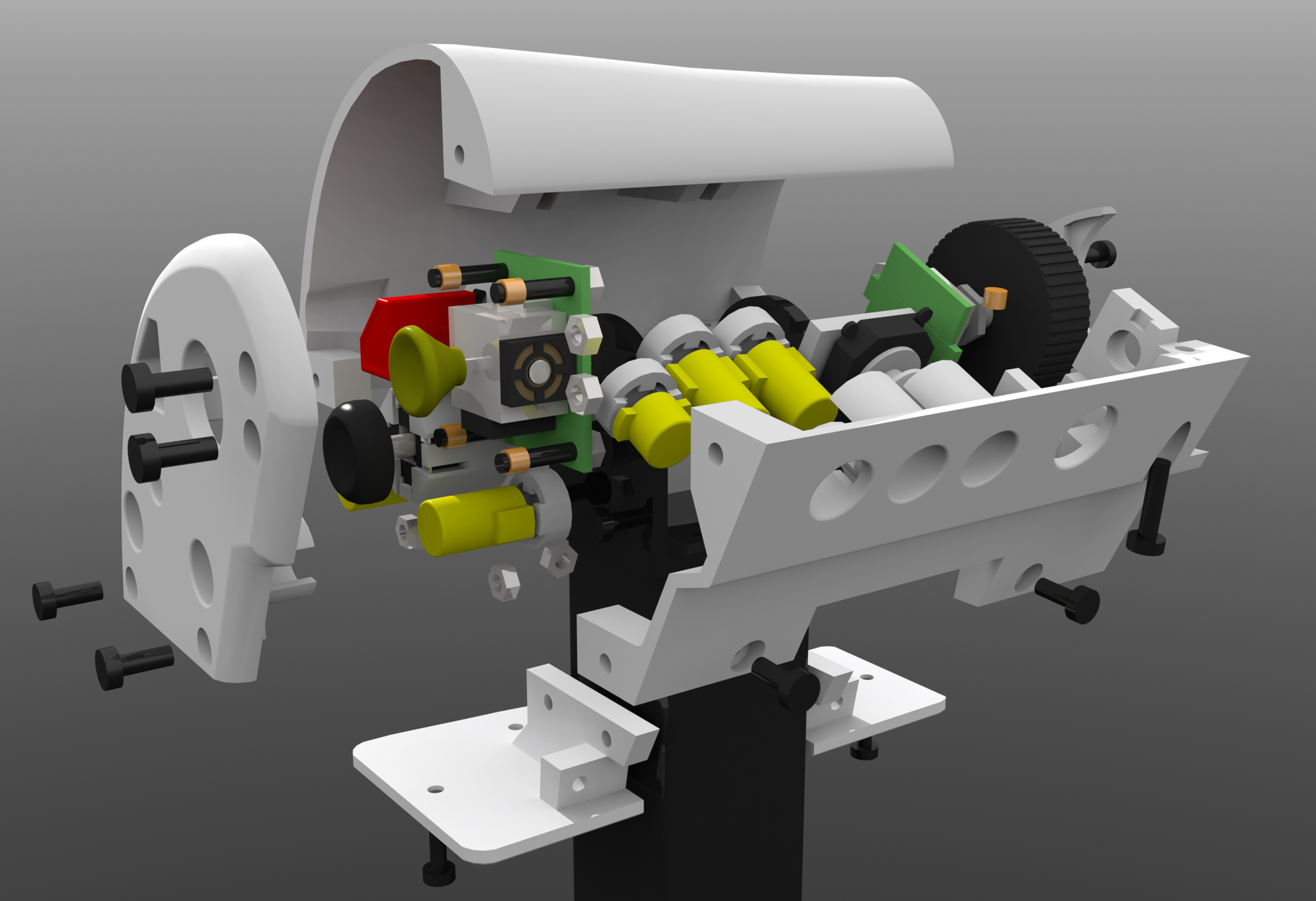
Joystick axis
I’ve gotten a lot of inspiration from “Rob” that designed his own custom 3d printed HOTAS: https://www.simplicate.info/building-my-own-hotas-controller/ Seems the two of us are pretty unique in this endeavor at least from looking around online, a lot of people weak HOTAS setups or make mounts for them, but finding any reference of people actually making a HOTAS setup is rare. Sadly he hasn’t released anything but descriptions and pictures because he’s still working on it and want to make a more polished and presentable set of instructions and 3d models etc at a later date. I really like several aspects of his design:
- 2 symmetrical handles
- Different motion
- Looks sturdy with smart use of non-printed “vitamins” like metal ball bearings, large metal screws, metal pipes, springs etc.
Main points I’ll deviate though is that I’ll have a lot more buttons/switches and I want a sliding throttle instead of a lever style one.
I already have basically all the parts to make the joystick already if I use potentiometers, I’m tempted to get hall effect sensors though.
I’m not sure if I want to use a spring and push plate design for the centering though, not sure if it will feel good to use, might be easier to use tension springs, also considering how easy it would be to source a 20mm+ diameter spring, I have several from my x55 (comes with 4 for different amounts of tension) but if I want this design to be readily reproducible a spring like that might be too hard to source, we’ll see.
Throttle Axis
The linear throttle axis could be done using 2020 v-slot and v-slot wheels: 
using the same components that go into my next 3d printer a gt2 timing belt going to pulley on a potentiometer/rotary encoder can be used to read the throttle position, adding a flywheel on the idler and potentiometer could be done to improve smoothness, other translations can be done using an analog thumb-stick, should have a concave head.
Potentiometer might not work due to the long range of motion (15-18cm~) and the limited fidelity of arduino’s analog inputs (8bit = 1024 possible values) might have to gear it out so the pot turns at a different rate than the pulley but then we’re getting into pretty complex and failure prone printed gearing etc.
Throttle Bump(s):


